

Quick Answer
The speed of an محرك EC FFU (fan filter unit) is usually controlled via the motor’s integrated electronic controller rather than by adjusting the AC supply frequency directly. The most common methods are 0–10 VDC analogue control, pulse width modulation (PWM), Modbus/RS485 communication, or an onboard/manual potentiometer. Depending on the EC motor and FFU controller, commercial FFU documentation confirms that these methods can provide continuous or programmable speed adjustment.
For cleanroom applications, however, it is usually not the best strategy to simply set the highest possible motor speed. A better approach is to control the required airflow or pressure because filter loading and system resistance can change over time. Research on feedback-controlled FFUs found that closed-loop airflow control maintains a more stable airflow rate than fixed-speed operation.
What Is an EC Motor FFU?
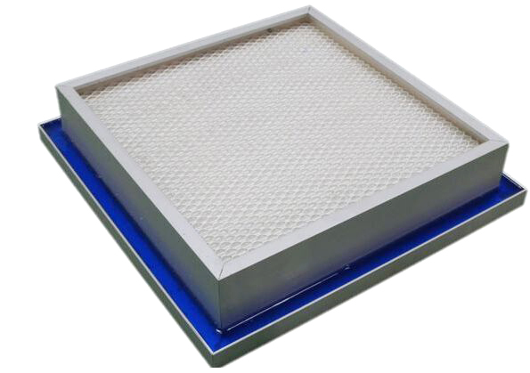
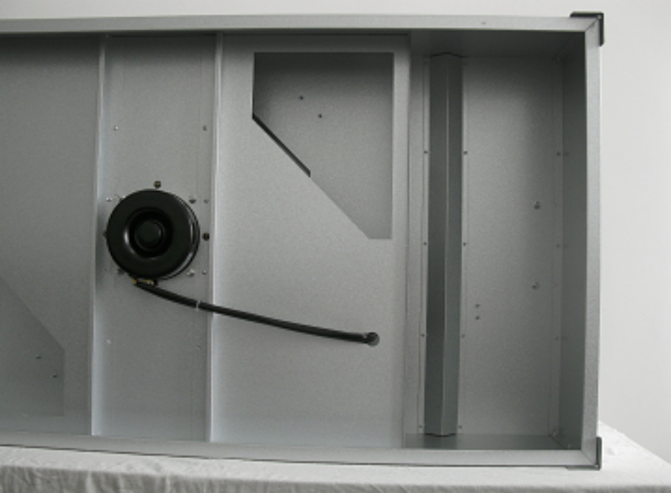
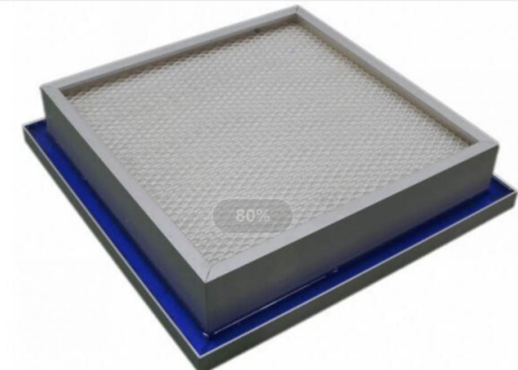
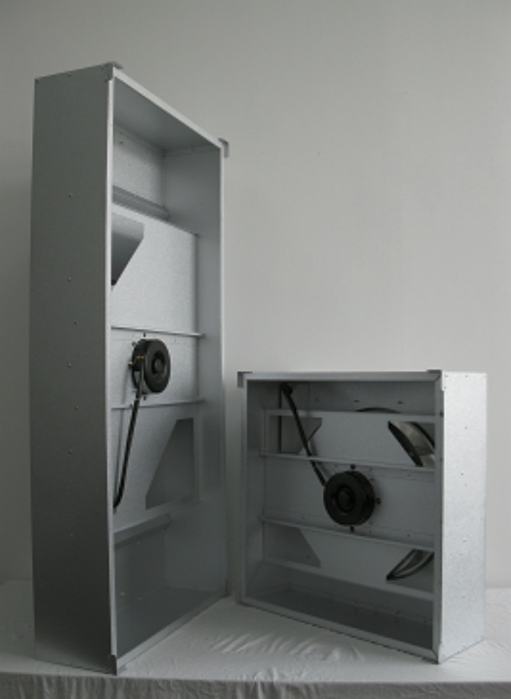
An EC motor fan filter unit (FFU) combines a fan and a filter in a single housing, along with an electronically commutated motor and integrated electronic speed control. FFUs typically contain a fan, an EC motor, a housing, a filter section, and control electronics. HEPA or ULPA filtration is used according to the cleanroom’s cleanliness requirements. Modern FFU designs may support continuous 0–10 VDC control or digital Modbus communication.
The main difference between an EC motor FFU and a traditional fixed-speed AC FFU is the ability to electronically adjust the motor output. Rather than relying on a simple multi-speed switch or running the motor continuously at its rated speed, the controller can adjust the fan speed in response to a voltage signal, pulse width modulation (PWM) command, digital communication, or feedback from another sensor. This is particularly valuable in cleanrooms because airflow requirements rarely remain identical under different operating conditions.
Furthermore, the relationship between fan speed and cleanroom airflow is not completely linear. As the HEPA filter becomes loaded with particles, its pressure drop can increase. Changes in duct or room resistance can have a similar effect. Consequently, maintaining the same motor speed does not necessarily guarantee the same delivered airflow. A 2007 study of feedback-controlled fan-filtered units (FFUs) found that conventional fixed-speed operation could result in undesirable airflow variation, whereas a feedback-controlled system can adjust the motor speed to maintain a preset airflow rate.

Why Control the Speed of an EC Motor FFU?
Speed control serves several purposes beyond simply adjusting the speed of the fan. In a cleanroom, the aim is usually to achieve the required airflow velocity, air-change rate, pressure relationship, particle control performance, and acoustic environment, while avoiding unnecessary energy consumption.
For instance, an FFU may operate at a relatively high speed during initial commissioning or when a greater airflow rate is required in the room. During normal production, the required airflow may be lower. During unoccupied periods, a facility may reduce airflow further while still meeting the minimum conditions required by its operating procedures. EC motors can modulate their output, enabling the FFU to respond to these changing requirements without repeatedly switching between full-speed operation and shutdown.
This is where energy savings become relevant. Fan power is strongly affected by operating speed, so reducing speed can produce a disproportionately large reduction in fan energy consumption under suitable conditions. However, the exact savings depend on factors such as the fan curve, system resistance, motor efficiency, filter pressure drop, and control strategy. Therefore, manufacturers should avoid treating a single percentage as universally applicable.
Control the EC Motor FFU with a 0–10 V Signal
The 0–10 VDC control signal is one of the most common methods of adjusting an EC motor fan-assisted unit (FFU).
The principle is straightforward: an external controller generates a low-voltage analogue signal that the EC motor’s internal controller interprets as a speed or demand command. While the relationship may be approximately proportional depending on the specific motor, the actual minimum speed, maximum speed, start-up threshold, and signal interpretation must always be confirmed in the manufacturer’s datasheet.
For instance, Mechatronics’ EC fan documentation describes a 0–10 VDC input, where 0 V corresponds to 0 RPM, approximately 1 V corresponds to minimum operation, and 10 V corresponds to full speed. However, this is just one example; other EC motors can use different voltage-to-speed curves.
A typical control architecture looks like this:
BMS/PLC/speed controller → 0–10 V signal → EC motor controller → motor → fan → airflow.
The advantage of 0–10 V is its simplicity. It can be integrated into a PLC, building management system, analogue controller, potentiometer, or dedicated FFU controller without the need for a complex digital network.
For a small cleanroom with relatively few FFUs, this can be an economical approach. However, for a large cleanroom with hundreds of units, individual analogue wiring can become more complicated, which is one reason why networked control is attractive.
Use PWM to Control EC Motor FFU Speed
PWM (pulse width modulation) is another method of controlling EC motor speed.
Rather than continuously changing the DC voltage, the controller sends a pulsed signal with a specific duty cycle. The EC motor’s internal electronics interpret this signal as a speed command.
PWM can provide precise electronic control and is particularly useful when the system controller already communicates using digital signals. However, the PWM frequency, voltage level, duty cycle range, signal polarity, and wiring requirements are not universal.
Some EC motor controllers specify dedicated PWM input characteristics, while others may only accept 0–10 V or a proprietary signal. Therefore, connecting a generic PWM source to an EC motor without checking the manufacturer’s electrical specifications may result in the motor operating incorrectly or even damage to the control input.
For original equipment manufacturers (OEMs) developing an EC motor fan filter unit (FFU), PWM is most useful when the motor controller and central control system are designed around it from the beginning. The interface should be specified alongside the motor, rather than being an afterthought.
Control an EC Motor FFU Through Modbus
For larger cleanrooms, Modbus RTU over RS485 provides a more scalable approach.
Rather than sending one analogue signal to each FFU, a network controller can communicate with multiple FFUs via a shared communication bus. Each unit is assigned an address, enabling the central system to identify and control the FFUs individually.
A typical architecture is as follows:
BMS/PC/PLC → RS485 network → FFU controller → EC motor.
ACDT’s current FFU product supports group monitoring and control via an RS485 Modbus connection. Its FFU design uses a variable-speed EC motor and provides centralised management capabilities.
Modbus-based control can provide much more than a simple speed command. Depending on the controller, the system may expose parameters such as:
- Motor speed
- Operating status
- Alarm condition
- Fault code
- Speed command
- Current or power
- Operating hours
- Sensor readings
- Airflow or pressure feedback
This makes Modbus particularly useful for large cleanroom installations, where operators need to monitor many FFUs from a central interface.
A commercial FFU controller manual documents three operating approaches: manual adjustment, 0–10 V analogue control and Modbus RTU, and also describes closed-loop control using airflow- or pressure-related sensors.
Use a Manual Potentiometer for Simple EC FFU Speed Adjustment
Not every installation requires a PLC or BMS.
For standalone FFUs or small cleanrooms, a manual potentiometer provides a simple way to adjust the speed. Turning the potentiometer changes the control signal supplied to the EC motor, enabling the operator to adjust the fan’s output accordingly.
This approach is particularly useful during commissioning. An engineer can gradually adjust the FFU speed while measuring airflow velocity or differential pressure, and then determine an appropriate operating point.
However, the limitation is scalability. Manual potentiometers do not offer the same monitoring, data logging, automation, or remote management capabilities as networked control systems. For large facilities with dozens or hundreds of FFUs, centralised digital control is generally more practical.
EC Motor FFU Speed Control Methods Compared
| Control Method | Signal / Interface | Typical Application | Main Advantage | Main Limitation |
| Manual potentiometer | Analog voltage | Single or small number of FFUs | Simple and inexpensive | Limited automation |
| 0–10 VDC | Analog | Small/medium cleanrooms, BMS | Easy integration | Requires individual signal wiring |
| PWM | Pulse signal | OEM and electronic control systems | Precise digital-style control | Signal specifications vary |
| Modbus RTU | RS485 | Large cleanrooms | Centralized monitoring and control | More configuration required |
| Closed-loop airflow control | Sensor + controller | Precision cleanrooms | Maintains target airflow | Higher system complexity |
| Pressure feedback | Differential pressure sensor | Filter/loading compensation | Responds to resistance changes | Requires sensor calibration |
The important point is that the control method and control objective are different concepts. 0–10 V, PWM, and Modbus describe how the command reaches the motor. Airflow control, pressure control, and speed control describe what the system is trying to achieve.
Speed Control vs. Airflow Control: What Is Better?
This distinction is crucial for designing an EC motor FFU system.
Suppose an FFU is initially adjusted to 800 RPM to produce the required airflow through a new HEPA filter. After several months of operation, particles accumulate in the filter, and its resistance increases. If the motor speed remains at 800 RPM, the airflow may decrease.
In a simple open-loop system, the controller is unaware that the airflow has changed. It only maintains the motor command.
A closed-loop system works differently:
Target airflow → Measured airflow → Controller → Motor speed adjustment → Measured airflow.
If the measured airflow drops below the target, the controller can increase the motor speed. Conversely, if the measured airflow becomes excessive, the controller can reduce the speed.
This principle was demonstrated in research on smart fan-filtered units (FFUs). In the study, the system measured pressure at the FFU inlet, calculated the airflow, and compared it with the assigned target. It then adjusted the motor speed accordingly. The researchers reported that the system could quickly reach preset airflow rates and maintain stable airflow despite changes in environmental loading.
For high-performance cleanrooms, this approach is generally more effective than simply specifying a fixed RPM.
Use Differential Pressure Feedback
A differential-pressure sensor can also be used to enhance the control of FFUs.
The sensor measures the pressure difference across a relevant section of the airflow path. When filter or system resistance changes, the controller uses the pressure signal to determine whether the fan needs to compensate.
This is particularly useful for applications where maintaining a predictable pressure relationship is important.
However, pressure does not exactly correspond to airflow. A particular pressure reading does not necessarily correspond to a single airflow rate in all conditions. Fan curves, filter resistance, air density, and system geometry all influence this relationship.
Therefore, when constant airflow is required, direct airflow measurement or a properly calibrated flow-estimation method may be preferable.
How Does 0–10 V Control Affect EC Motor Speed?
It is a common misconception that a 5 V signal always equates to exactly 50% motor RPM.
This is not necessarily true.
It is up to the EC motor controller to determine how the input signal is translated into motor output. One motor may use a nearly linear relationship, while another may have a minimum startup voltage or operating speed, or a non-linear control curve.
For this reason, the correct procedure is to obtain the motor’s control specification and identify the following:
- Minimum input voltage
- Maximum input voltage
- Minimum operating speed
- Maximum operating speed
- Startup threshold
- Signal reference/ground requirements
- Whether 0 V means stop or minimum speed
- Whether the input can be configured
- Whether external enable/disable is required
A current EC fan control reference describes a 0–10 V system in which the fan responds to a changing control voltage. However, it explicitly notes that this is part of the particular fan design.
Therefore, never assume that 0–10 V is universally proportional to 0–100% RPM.
How to Set the Correct Speed During Commissioning?
The best way to determine the correct operating speed is to start from the required cleanroom airflow rather than from an arbitrary RPM value.
A practical commissioning sequence is:
Step 1: Confirm the FFU specification
Check the fan performance curve, rated airflow, available static pressure, motor speed range, and filter specification.
Step 2: Check the filter condition
A new HEPA or ULPA filter and a loaded filter can have substantially different resistance characteristics. Record the condition during commissioning.
Step 3: Start at a conservative speed
Begin with a low-to-moderate control command and allow the FFU to stabilize before taking measurements.
Step 4: Measure airflow velocity or airflow volume
Use calibrated measuring equipment appropriate for the FFU and cleanroom configuration.
Step 5: Adjust the EC motor command
Increase or decrease the 0–10 V, PWM, Modbus, or manual setting until the required airflow condition is reached.
Step 6: Verify uniformity
Do not rely on a single measurement point. Airflow uniformity across the FFU outlet is important, particularly for applications requiring controlled unidirectional airflow.
Step 7: Record the operating condition
Document the control signal, measured airflow, pressure, motor speed, and relevant environmental conditions.
Step 8: Consider closed-loop control
If airflow must remain stable despite filter loading or changing system resistance, use a feedback-based strategy rather than a fixed speed.
What Happens If the EC Motor FFU Runs Too Fast?
Running an FFU at its maximum speed does not necessarily produce better results.
While higher speed generally increases airflow, it can also increase electrical consumption and acoustic output. It may also disrupt the intended airflow pattern if the cleanroom was designed for lower velocity airflow.
In a cleanroom, excessive airflow can create turbulence or undesirable interactions with equipment, operators or neighbouring airflow zones. It may also increase operating costs without meaningfully improving contamination control.
This is why FFU selection guides commonly emphasise surface velocity, static pressure, power consumption, filter resistance and airflow uniformity together, rather than treating motor speed as the only performance parameter.
The correct goal is sufficient airflow, not maximum airflow.
What Happens If the EC Motor FFU Runs Too Slowly?
The opposite problem can be even more serious.
If fan speed is reduced too far, the FFU may fail to provide the required airflow velocity or room air-change rate. Depending on the cleanroom design, this can affect contamination control, pressure relationships, and process requirements.
An excessively low setting can also become problematic if filter resistance increases later. A system operating close to its minimum capacity may have insufficient reserve to compensate for increased resistance.
For this reason, the operating point should include an appropriate margin while remaining within the cleanroom’s validated operating requirements.
How to Control Multiple EC Motor FFUs?
Controlling each FFU independently through local potentiometers is inefficient for a large cleanroom.
A centralised system can divide FFUs into groups or zones and provide:
Central controller → communication network → individual FFU controllers → EC motors.
Each unit can receive its own speed command and report its operating status back to the central system.
Modern FFU systems can support functions such as centralised start/stop, speed adjustment, fault monitoring, operating status display and scheduled operation. One current FFU control system, for example, enables centralised control of FFU operation, speed and fault status via a computer or touchscreen interface.
This approach also makes maintenance easier for large semiconductor, pharmaceutical, biotechnology and precision manufacturing facilities because operators can identify abnormal units without physically checking every FFU.
Energy Optimization of an EC Motor FFU
Energy optimisation should begin with the recognition that fan speed and airflow demand are dynamic variables.
If a cleanroom requires less airflow under certain operating conditions, reducing the speed of the fan can reduce energy consumption. EC motors are particularly well suited to this approach, as their integrated electronics allow for continuous speed modulation.
However, energy savings should not be achieved by reducing airflow below the validated cleanroom requirement. The correct sequence is as follows:
1) Determine the minimum acceptable airflow.
2) Monitor actual conditions.
3) Modulate FFU speed.
4) Maintain required performance.
5) Avoid unnecessary airflow.
This approach is more robust than operating every FFU at a fixed high speed.
For large cleanrooms, even relatively small improvements in the operating points of individual FFUs can become significant when multiplied across hundreds or thousands of units. This is one reason why centra.
Common Problems When Controlling EC Motor FFU Speed
Problem 1: The Motor Does Not Respond to 0–10 V
Check whether the motor actually supports analog voltage control, whether the signal ground is correctly connected, and whether the controller is configured for analog mode. Some EC controllers require a separate enable signal or mode selection.
Problem 2: 5 V Does Not Produce 50% Speed
This is often normal. The voltage-to-speed relationship is manufacturer-specific and may include minimum-speed thresholds or nonlinear characteristics.
Problem 3: All FFUs Run at Different Airflows
Do not assume identical control signals will produce identical airflow. Filter resistance, fan manufacturing tolerances, installation conditions, and local pressure differences can cause variation.
Problem 4: Airflow Falls Over Time
Check filter loading and system resistance. If the FFU is operating in open-loop speed control, consider adding airflow or pressure feedback.
Problem 5: The FFU Is Too Noisy at High Speed
Check whether the fan is operating above the required airflow point, and inspect vibration, impeller balance, filter condition, mounting, and duct/ceiling interactions.
Recommended EC Motor FFU Control Strategy
| Cleanroom Requirement | Recommended Control Strategy | Why |
| One standalone FFU | Manual potentiometer or 0–10 V | Simple adjustment |
| Small cleanroom | 0–10 V centralized control | Easy BMS integration |
| Medium cleanroom | 0–10 V or Modbus | Balance simplicity and monitoring |
| Large cleanroom | Modbus/RS485 network | Centralized control and diagnostics |
| Constant airflow requirement | Airflow feedback | Compensates for changing resistance |
| Constant pressure requirement | Differential-pressure feedback | Maintains pressure target |
| Variable production schedule | Programmable speed control | Matches airflow to operating conditions |
| High energy-efficiency target | EC + demand-based modulation | Avoids unnecessary fan speed |
| Pharmaceutical/precision environment | Closed-loop control + monitoring | Better process consistency |
FAQ: EC Motor FFU Speed Control
- How do you control the speed of an EC motor FFU?
The most common methods are 0–10 VDC, PWM, Modbus/RS485, or a manual potentiometer, depending on the EC motor controller. Always check the motor’s control-input specification before connecting an external controller.
- Can an EC motor FFU be controlled by 0–10 V?
Yes, many EC motor FFUs support 0–10 VDC analog speed control. The exact relationship between voltage and motor speed varies by manufacturer and model.
- Can I use PWM to control an EC motor FFU?
Yes, if the motor controller provides a compatible PWM input. The required PWM voltage, frequency, duty-cycle range, and wiring should be confirmed from the manufacturer’s technical documentation.
- Is Modbus better than 0–10 V for FFU control?
Modbus is generally more powerful for large installations because it can provide centralized speed control, monitoring, alarms, and other operating data. For a small number of FFUs, 0–10 V may be simpler and more economical.
- Should FFU speed be controlled by RPM or airflow?
For most cleanroom applications, airflow is the more meaningful control target because the required cleanroom performance depends on delivered airflow rather than motor RPM itself. Feedback-controlled FFU research demonstrates that adjusting motor speed according to measured airflow can maintain more stable airflow when system conditions change.
- Does increasing EC motor FFU speed improve cleanroom cleanliness?
Not necessarily. Higher speed increases airflow, but excessive airflow can increase energy use and may disturb the intended airflow pattern, so the FFU should be operated at the validated airflow required by the cleanroom design.
Conclusion
Controlling the speed of an EC motor fan filter unit (FFU) is technically straightforward because the EC motor integrates electronic commutation and speed control functionality into the motor system. The most common interfaces are 0–10 V DC, pulse width modulation (PWM), Modbus/RS485, and manual potentiometer control. The most appropriate interface depends on the scale of the cleanroom and its automation requirements.
For small FFU installations, 0–10 V control is often the simplest solution. For a large cleanroom with many FFUs, Modbus-based centralised control provides much greater visibility and flexibility. When maintaining a specific airflow is critical, the most advanced approach is to add airflow or pressure feedback, which allows the controller to automatically adjust the speed of the EC motor as filter resistance and room conditions change.
The key engineering principle is therefore:
Do not control an EC motor FFU simply to achieve a particular RPM; control it to achieve the required airflow and cleanroom performance.
This distinction becomes increasingly important as HEPA filters become loaded, room conditions change, production processes vary, and energy efficiency requirements become stricter. Research on intelligent FFUs has already demonstrated that feedback-based speed adjustment improves airflow uniformity and maintains preset airflow rates more effectively than conventional fixed-speed operation.
For manufacturers, system integrators and cleanroom engineers, the optimal architecture is typically a combination of an EC motor, an appropriate speed control interface, calibrated airflow/pressure measurement and centralised monitoring where required. This approach provides the flexibility to balance cleanliness, airflow stability, acoustic performance, energy consumption and long-term operating costs, rather than treating motor speed as an isolated parameter.