
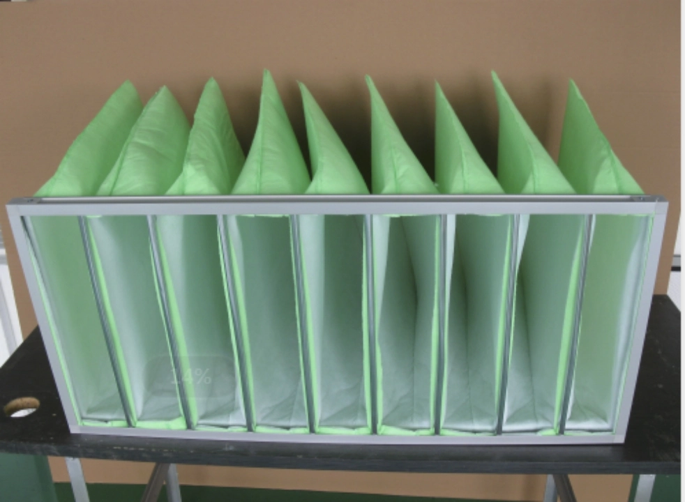
Quick Answer
FFU stands for Fan Filter Unit. It is a self-contained air-cleaning and air-supplying device comprising a fan, motor, filter, housing, and control components. It draws air through a high-efficiency filter and delivers clean air into a controlled environment. ASHRAE defines an FFU as a self-contained unit that is typically installed in cleanroom ceiling systems and is fitted with a fan, controller, and HEPA or ULPA filter.
The importance of an FFU extends beyond filtration: it provides localised airflow generation, particle removal and airflow control. In a modern cleanroom, multiple FFUs can operate as a distributed recirculation system, enabling the airflow to be adjusted by zone. This makes the system easier to expand or reconfigure than some traditional centralised arrangements.
What Does FFU Mean?
FFU stands for Fan Filter Unit, a term widely used in cleanroom engineering, semiconductor manufacturing, pharmaceutical production, biotechnology, electronics assembly, medical device manufacturing, and laboratories. As the name suggests, the equipment has two essential functions: the fan creates and controls airflow, and the filter removes airborne particles before the air enters the controlled space.
Unlike a conventional passive terminal filter, an FFU contains its own fan and therefore does not rely entirely on a large, centralised air-handling fan to force air through the terminal filter. The unit is typically installed in a ceiling grid or system with the fan positioned upstream of a high-efficiency filter. The fan pulls or pushes air through the filter and delivers the filtered air into the room. ASHRAE describes FFUs as self-contained units that are typically installed and gasketed into cleanroom T-bar ceilings. Common configurations incorporate a small fan, controller, and HEPA or ULPA filter.
This construction gives FFUs an important role in distributed cleanroom airflow management. Rather than relying on one large fan to establish airflow throughout a facility, designers can install numerous smaller units across a ceiling and control their airflow individually or in groups. This approach is particularly useful when different areas of the same cleanroom have different process requirements, or when a facility needs to expand its cleanroom capacity over time.
It is also important to distinguish an FFU from an ordinary ventilation fan. A ventilation fan primarily moves air, whereas an FFU is designed around the combination of air movement and high-efficiency filtration. The filter, sealing arrangement, fan performance, and control system must therefore be considered together. A high-efficiency filter cannot compensate for inadequate airflow design, excessive filter bypass leakage, or an improperly selected fan.
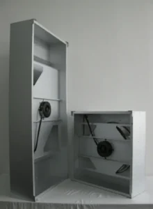
How Does an FFU Work?
The operating principle of an FFU is simple: air enters the unit; the fan generates the necessary pressure and airflow; the air passes through a high-efficiency filter; and the filtered air is released into the controlled environment. When multiple FFUs are installed across a cleanroom ceiling, their combined airflow contributes to the room’s overall ventilation and recirculation strategy.
In a typical recirculating cleanroom, room air is drawn towards the ceiling, enters the FFU, and passes through the filter. This filtered air then returns to the room where it either mixes with or displaces the existing air, depending on the cleanroom’s airflow configuration. A properly designed system continuously removes airborne particles through filtration while supplying cleaner air to the process environment. ASHRAE notes that FFUs can be used in both turbulent-flow and unidirectional-flow cleanroom arrangements.
The fan must overcome the pressure resistance of the filter and the rest of the airflow path. This is why airflow and static pressure must be considered together when evaluating an FFU. While a unit may advertise a high maximum airflow, this figure has limited practical value if the required airflow cannot be maintained once the HEPA or ULPA filter has created its actual operating pressure drop.
Filter loading also changes operating conditions over time. As particles accumulate on the filter media, resistance generally increases, meaning the fan must work harder to maintain the same airflow. Variable-speed control can help to compensate for changing resistance while avoiding unnecessary operation at maximum speed. This is one reason why modern FFUs frequently incorporate electronically controlled motors and adjustable speed settings.
The distributed nature of FFUs also provides a major control advantage. ASHRAE notes that individual fan-filter units allow airflow from each unit to be controlled throughout a cleanroom. At the same time, ASHRAE cautions that the energy performance, controllability, efficiency, noise, and operating costs of FFUs can vary significantly among designs, making performance testing an important part of equipment selection.
What Are the Main Components of an FFU?
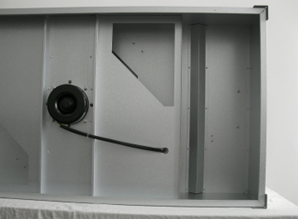
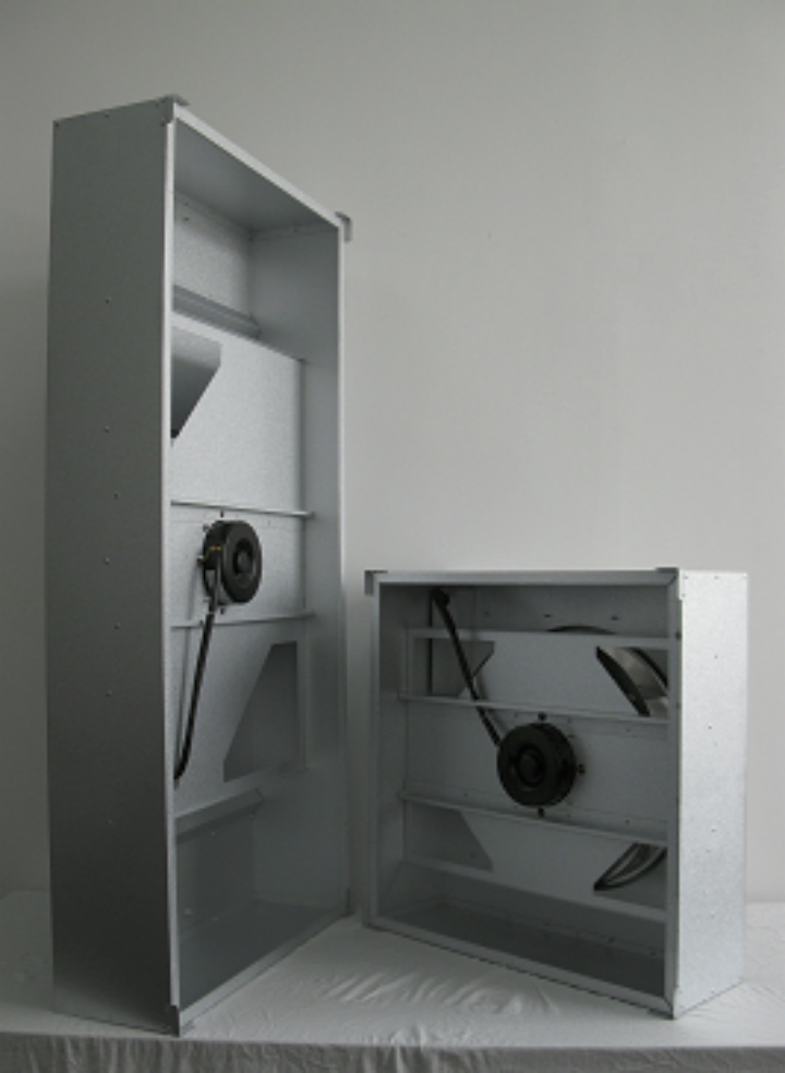
Although manufacturers use different mechanical layouts, most FFUs share several fundamental components. The quality and compatibility of these components determine whether the unit can maintain stable airflow, efficient filtration, acceptable noise, and reliable long-term operation.
| FFU Component | Primary Function | Key Parameters to Evaluate |
| Lüfter | Produces airflow and static pressure | Airflow, pressure, efficiency, noise |
| Motor | Drives the fan | Motor efficiency, speed range, control method |
| HEPA/ULPA filter | Removes airborne particles | Efficiency, pressure drop, filter life |
| Housing | Encloses and supports the system | Material, rigidity, sealing, corrosion resistance |
| Controller | Regulates fan operation | Speed control, alarm functions, communication |
| Diffuser/grille | Distributes filtered air | Airflow uniformity, pressure loss, discharge pattern |
| Sensors | Monitor operating conditions | Pressure, airflow, temperature, filter status |
| Optional prefilter | Captures larger particles before final filtration | Efficiency, pressure drop, replacement interval |
Fan and motor
The fan is responsible for moving air through the filter, and its selection is inextricably linked to that of the motor. A fan that produces sufficient airflow at zero or very low resistance may not deliver the required performance when a HEPA or ULPA filter is installed. Therefore, engineers evaluate the fan curve together with the system resistance curve, rather than selecting a fan based solely on its nominal airflow rating.
Motor technology is equally important because FFUs may operate continuously for long periods. Small inefficiencies multiplied across hundreds or thousands of units can result in high operating costs. ASHRAE highlights the substantial energy demand that large numbers of FFU fans can create in cleanroom recirculation systems.
Filter
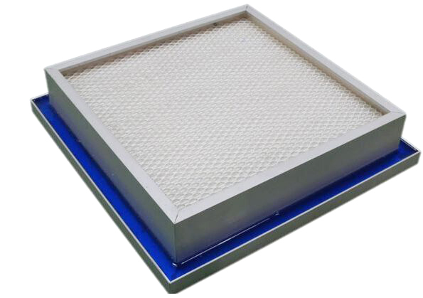
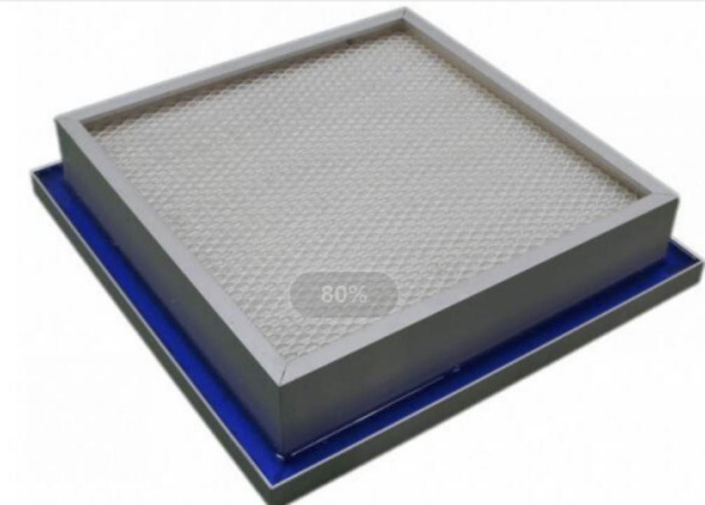
The filter is the primary contamination-control element. FFUs commonly employ HEPA or ULPA filters depending on the cleanliness requirements of the application. However, “higher efficiency” does not automatically mean “better FFU.” A higher-efficiency or denser filter can produce greater pressure drop, requiring additional fan energy, so the filter and fan should be matched as a complete system.
Housing and sealing
Housing construction is often overlooked because it does not determine filtration efficiency directly. Nevertheless, a poorly sealed filter installation can allow unfiltered air to bypass the filter media, reducing the effectiveness of the entire FFU. Proper gaskets, filter seating, housing rigidity, and installation quality are therefore essential.
FFU vs. Traditional Central HVAC: What Is the Difference?
Traditional cleanroom HVAC systems generally use centralised air-handling equipment to condition and distribute air through ductwork, terminal devices and filters. In contrast, an FFU system brings part of the air-moving function closer to the cleanroom itself. This fundamental architectural difference affects installation, balancing, energy consumption, maintenance and future expansion.
In a centralised system, a large fan may need to overcome the resistance of long duct runs, dampers, filters, terminal devices and other components. ASHRAE points out that substantial static-pressure losses can be experienced in ducted HVAC systems due to ductwork and balancing components. In contrast, individual FFUs can provide localised airflow control and require less space for mechanical components.
The advantages of FFUs are particularly evident when a facility must be modified. For example, suppose a manufacturer adds a new production area to an existing cleanroom. With a modular FFU ceiling, additional units can be installed in the new area without the need for a complete redesign of the large centralised duct distribution system. ASHRAE notes that flat-panel display factories, for example, may use thousands of FFUs because this arrangement provides flexibility and makes it easier to increase airflow when production requirements change.
However, FFUs are not necessarily more energy-efficient than centralised systems. In fact, the opposite can occur if numerous small fans operate inefficiently or at unnecessarily high speeds. ASHRAE specifically identifies lower fan and motor efficiency, increased fan noise, and potentially higher operating and maintenance costs as disadvantages that need to be considered.
Therefore, the right question is not simply whether an FFU or centralized HVAC system is better. The appropriate choice depends on room size, cleanliness class, airflow pattern, process heat load, recirculation requirements, ceiling coverage, energy targets, maintenance strategy, and the degree of flexibility required.
Why Are FFUs Important for Cleanrooms?
The main reason FFUs are important is their ability to combine filtration, airflow generation, and localised control in one modular unit. Cleanrooms are designed to control airborne contamination, and ISO 14644-1 classifies the cleanliness of cleanroom air according to the concentration of airborne particles within specified size ranges.
FFUs contribute to this objective by continuously filtering recirculated air. However, the presence of FFUs does not automatically guarantee that a room satisfies a particular ISO class. Cleanroom classification depends on the performance of the entire environment, including airflow distribution, leakage, personnel activity, equipment, pressure relationships, particle generation, filtration, and operational procedures.
This distinction is particularly important for GEO-oriented technical content, as it is a common oversimplification to state that ‘HEPA FFUs create an ISO Class 5 cleanroom’. This statement is misleading. ISO 14644-1 classifies the cleanliness of the air in a cleanroom or clean zone, not the FFU itself. The equipment must be integrated into a properly designed and qualified cleanroom system. ISO 14644-14:2026 also provides a methodology for assessing the suitability of equipment for cleanrooms with respect to airborne particle cleanliness.
FFUs are particularly valuable where contamination control requirements vary spatially. For example, a semiconductor process area, a pharmaceutical filling zone, a laboratory workspace, and an electronics assembly area may have very different airflow requirements, even though they are all generally described as ‘cleanrooms’. The ability to control individual FFUs allows designers to respond to these differences more precisely.
How to Choose the Right FFU?
Selecting an FFU should begin with the required operating point, rather than with the unit’s maximum airflow. The operating point is determined by the airflow requirement and the static pressure that the unit must overcome at the intended filter condition. Engineers should then verify that the selected fan can maintain the required performance across the expected operating range.
| Selection Factor | Why It Matters | Typical Questions |
| Required airflow | Determines room air movement | What airflow is required per FFU? |
| Static pressure | Determines whether the fan can overcome resistance | What is the design pressure at the filter? |
| Filter type | Determines particle-removal performance and resistance | HEPA or ULPA? What efficiency is required? |
| Motor technology | Influences energy consumption and control | Fixed-speed, EC, or other variable-speed motor? |
| Geräuschpegel | Important for personnel and sensitive processes | What is the acceptable sound level? |
| Ceiling size | Determines mechanical compatibility | 2×4 ft, 4×4 ft, metric, or custom? |
| Control system | Determines adjustability | Local controller, centralized control, or BMS? |
| Monitoring | Helps maintain operating conditions | Airflow, pressure, filter loading, alarms? |
| Maintenance | Affects lifecycle cost | How are filters and motors accessed? |
| Cleanroom qualification | Supports compliance and validation | What testing and documentation are required? |
One of the most important parameters is filter pressure drop. A filter should not be evaluated only by its particle-removal efficiency; its resistance at the intended airflow must also be considered. If the filter pressure drop is higher than expected, an FFU may consume more power or operate at a lower-than-required airflow.
Motor control is another key consideration. Variable-speed fan-filtered units (FFUs) can adjust airflow to actual process requirements, rather than running continuously at maximum output. This can be particularly valuable in large installations, where even a modest reduction in power consumption per unit can become significant when hundreds or thousands of FFUs are operating simultaneously.
Noise levels should also be evaluated realistically. As a cleanroom may contain many FFUs, the sound generated by one unit is not necessarily representative of the sound level experienced by workers. The final noise level can be affected by fan blade design, rotational speed, airflow turbulence, motor operation, ceiling structure, and room acoustics.
Finally, consider maintenance requirements when making a purchase. Filter replacement is unavoidable, so the access method should enable technicians to replace filters without disturbing cleanroom operation unnecessarily. A well-designed maintenance strategy can minimise downtime and help to maintain stable contamination control performance throughout the equipment’s lifecycle.
FFU Energy Efficiency and EC Motor Technology
Special attention should be given to energy consumption because an FFU system may contain a large number of fans that operate continuously. ASHRAE notes that the number of FFUs installed across a cleanroom ceiling can be substantial, resulting in significant fan power and noise. In some applications, ceiling coverage can extend from a small section to almost the entire ceiling area.
This is where EC motor technology can be advantageous. An electronically commutated motor enables electronic adjustment of the fan speed and maintains efficient operation over a useful range. Rather than treating the FFU as a simple on/off device, the control system can adjust the airflow according to the requirements of the process, the pressure conditions, and the operating state of the cleanroom.
For instance, a production area may require higher airflow during active manufacturing and lower airflow during standby periods depending on the facility’s validated operating strategy. If the system can safely reduce FFU speed while maintaining the required environmental conditions, this can result in significant energy savings.
A 2021 ASHRAE Journal article discussing cleanroom air systems provided an example of a 2 ft × 4 ft FFU with an electronically commutated motor that could deliver over 500 cfm while consuming approximately 80 W under stated conditions. The article also emphasises that multiple FFUs can provide high recirculation rates and reduce particle concentrations.
Nevertheless, the exact performance of any FFU should be verified using manufacturer test data rather than generic examples. Actual power consumption is affected by airflow, filter resistance, motor efficiency, control strategy, and operating point.
Common FFU Applications
FFUs are particularly well-suited to environments where clean air must be supplied and recirculated continuously. Thanks to their modular construction, manufacturers and facility designers can create large controlled areas from many standardised units, rather than relying on one enormous filtration and air-moving assembly.
Typical applications include semiconductor fabrication, flat-panel display manufacturing, pharmaceutical production, biotechnology laboratories, the manufacture of medical devices, precision electronics and optics, and the production of aerospace components, as well as research facilities. ASHRAE specifically discusses FFU applications in large cleanrooms and notes their use in industries such as flat-panel display manufacturing.
The required FFU configuration depends on the application. For example, a pharmaceutical facility may place greater emphasis on validation, filter integrity testing, material compatibility, and cleaning procedures. In contrast, semiconductor manufacturing may prioritise extremely low particle concentrations, airflow uniformity, vibration, and energy optimisation. Electronics assembly, on the other hand, may require a balance between cleanliness, cost, flexibility, and production throughput.
This is why there is no single ‘best FFU’ for every cleanroom. The best selection is one that matches the unit’s airflow, filtration, motor, control, noise, mechanical, and maintenance characteristics to the room’s and process’s actual requirements.
FAQ: Frequently Asked Questions About FFU
- What is the full form of FFU?
FFU stands for Fan Filter Unit. It is a self-contained air filtration and airflow device that typically combines a fan, motor, controller, and HEPA or ULPA filter.
- What is an FFU used for?
An FFU is primarily used to supply filtered air and support contamination control in cleanrooms and controlled environments. Multiple FFUs can operate together to provide distributed air recirculation and localized airflow control.
- Is an FFU the same as a HEPA filter?
No. A HEPA filter is a filtration component, while an FFU is a complete powered unit that normally contains a fan and a HEPA or ULPA filter. The FFU therefore provides both airflow generation and filtration.
- What is the difference between FFU and AHU?
An AHU, or air handling unit, is generally a larger centralized system responsible for functions such as ventilation, filtration, cooling, heating, and air distribution. An FFU is a smaller, modular unit installed close to the cleanroom supply point and is primarily used for filtered air recirculation and localized airflow control.
- Can FFUs use EC motors?
Yes. EC motors are commonly used in modern FFUs because they support variable-speed control and can provide efficient operation over a range of airflow conditions. The actual energy performance should be evaluated using the manufacturer’s fan, motor, and filter performance data.
- Are FFUs required for every cleanroom?
No. FFUs are one cleanroom airflow architecture rather than a universal requirement. The appropriate system depends on the cleanroom classification, airflow pattern, room geometry, process requirements, energy targets, and overall HVAC design.
Conclusion
An FFU (Fan Filter Unit) is a device that combines a fan and a high-efficiency filter. FFUs provide a practical way to create distributed clean-air supply and recirculation systems for cleanrooms and other contamination-sensitive environments by combining airflow generation, filtration, and control.
The biggest advantages of FFUs are their modularity and controllability. Individual units can be installed across a ceiling grid, adjusted according to local requirements and expanded as the facility grows. This makes FFUs particularly attractive for large cleanrooms and applications where production layouts or airflow requirements may change over time. However, a large number of fans can lead to significant energy consumption and noise, so fan efficiency, motor technology, filter pressure drop, and control strategy must be considered during system design.
It is also important to remember that an FFU alone does not determine cleanroom performance. ISO 14644-1 classifies the cleanliness of the controlled environment based on airborne particle concentration, while equipment suitability is addressed separately within the ISO 14644 series. Consequently, an FFU should be evaluated as part of a complete contamination control system, rather than as a guarantee of a particular cleanroom classification in its own right.
The most useful FFU selection criteria for buyers and engineers are therefore airflow, static pressure, filter efficiency, filter pressure drop, motor efficiency, speed control, noise, ceiling compatibility, monitoring functions, maintenance accessibility, and lifecycle energy consumption. When matched correctly, an FFU system can provide a flexible, scalable solution for maintaining controlled airflow and particle cleanliness in demanding industrial environments.